Latest
Vike SSR Rendering
Nov 11, 2023
Re-Engineering the OM617 Glow Plug Relay
Nov 04, 2023
Re-Engineering the OM617 Glow Plug Relay
November 4, 2023
Topics: Cars, Electronics, Mercedes, 300CD, 300D, ATTiny85
I was faced with an all too typical problem when driving an old car. A single point of failure; some part that has been working pretty much correctly for decades, decides to give up.
Such as it was with my Mercedes glow plug system. The typical amber glow emminating from the dashboard at the turn of the key, and the sound of the 40 year old diesel turning over after a couple seconds of cranking weren't there. Instead, they were replaced with a bright red alternator light and the endless sound of an engine cranking with no hope of firing on a 50 degree Farenheit fall evening.
The series glow plug system is a known week spot on early OM617 engines that were manufactured in the mid to late 70's. In the early 80's, the system was redesigned with the plugs wired in parallel. This brings two advantages...
1) There is a full 12V supplied to each plug, and given ohm's law we can get more power from each plug without rediculous amounts of current.
2) If any one glow plug fails, the remaining plugs will still work. In other words, they aren't an old string of Christmas lights anymore.
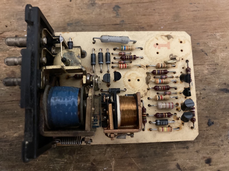
There were kits availiable to retrofit the series glow system, but there was one concern I had with this route. The factory glow plug relay was still utilized to pass current to the plugs. On the older versions, this routes lots of current (80A) over frail wiring that passes through the firewall and back. I decided to come up with a way to still utilize the factory relay wiring, but wire in a high current relay under the hood for passing controlling the plugs. Below is a picture of the business side of the old OM617 relay. We can improve this and reduce the fire hazard while we're at it.
To keep the function as factory as possible, I wanted the glow timer to automatically compensate for block temperature. This is something that the retrofit kits don't address. When it's very cold outside (cold being 30F/0C, here in NC) the plugs need to glow for a few seconds. When warm, they should only glow for a second. When the engine is hot, they shouldn't glow at all. Since the factory wiring already had the block sensor wired in, I didn't have to route anything else through the firewall. Rather than try to come up with an old-school R-C circuit that can compensate for sensor resistance and operate as a timer, I decided to throw a cheap microcontroller at it.
I am a fan of the 8 bit Atmel series microcontrollers. Prior to the pandemic, they were insanely cheap, availiable, and had just enough function packed into an 8 pin package to tackle simple jobs like this. Need a timer? AT-Tiny! Need to output a PWM signal? AT-Tiny! They can be used in the Arduino IDE/Framework, or programmed in plain old C. I prefer the latter, as you get to really understand how capable these things are. For this, I use PlatformIO to manage any libraries I need and run the avr-gcc compiler. Post-pandemic, supplies seem to be improving and the price is still reasonable for small quantity projects.
Since I don't need high accuracy on the timer, I'm going to utilize the onboard oscillator. This eliminates the need to take up two pins with an external oscillator. This is fine for this project, but things that need accurate timing will require it. The glow timer works by:
1) Doing an analog to digital conversion on the temperature sensor voltage.
2) Using the ADC value to compare against a lookup table stored in an array.
3) Using the return value from the lookup array to set up a timer.
From there, the logic is simple. Glow plugs on for x amount of time, then off. The program will continue to run with the output off until the power is cycled on the microcontroller (by action of turning the ignition off, and back on again).
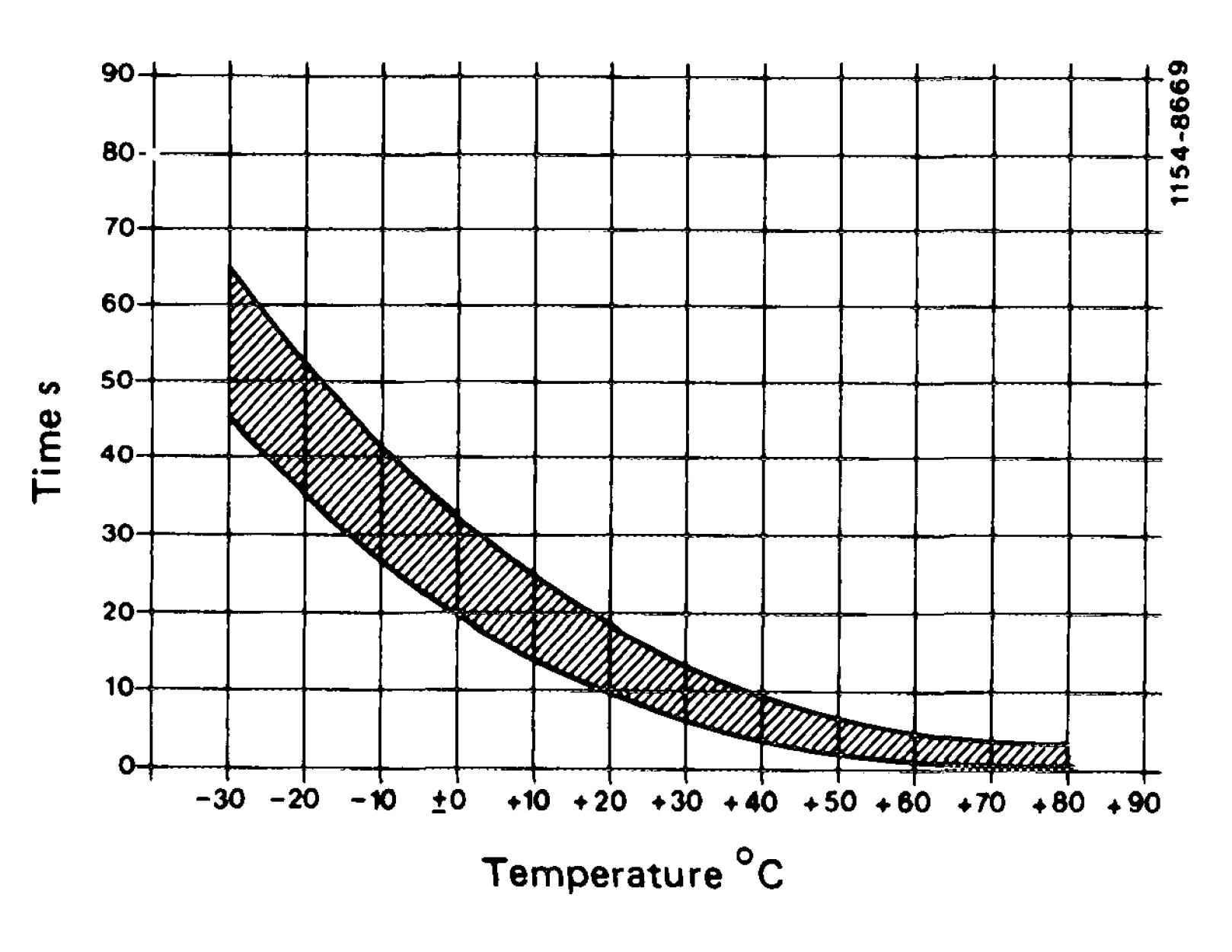
Now, how long do the plugs need to stay on? Since these are considered "fast" glow plugs, the time required is very different from the old plugs. Time to dig into some old documentation. At some point, Mercedes-Benz decided to release the old factory service manuals for the W123 chassis and OM617 series engines. Buried somewhere in the "preglow system" manual, I found comparisons of the two systems, along with the required pre-glow time based on block temperature.
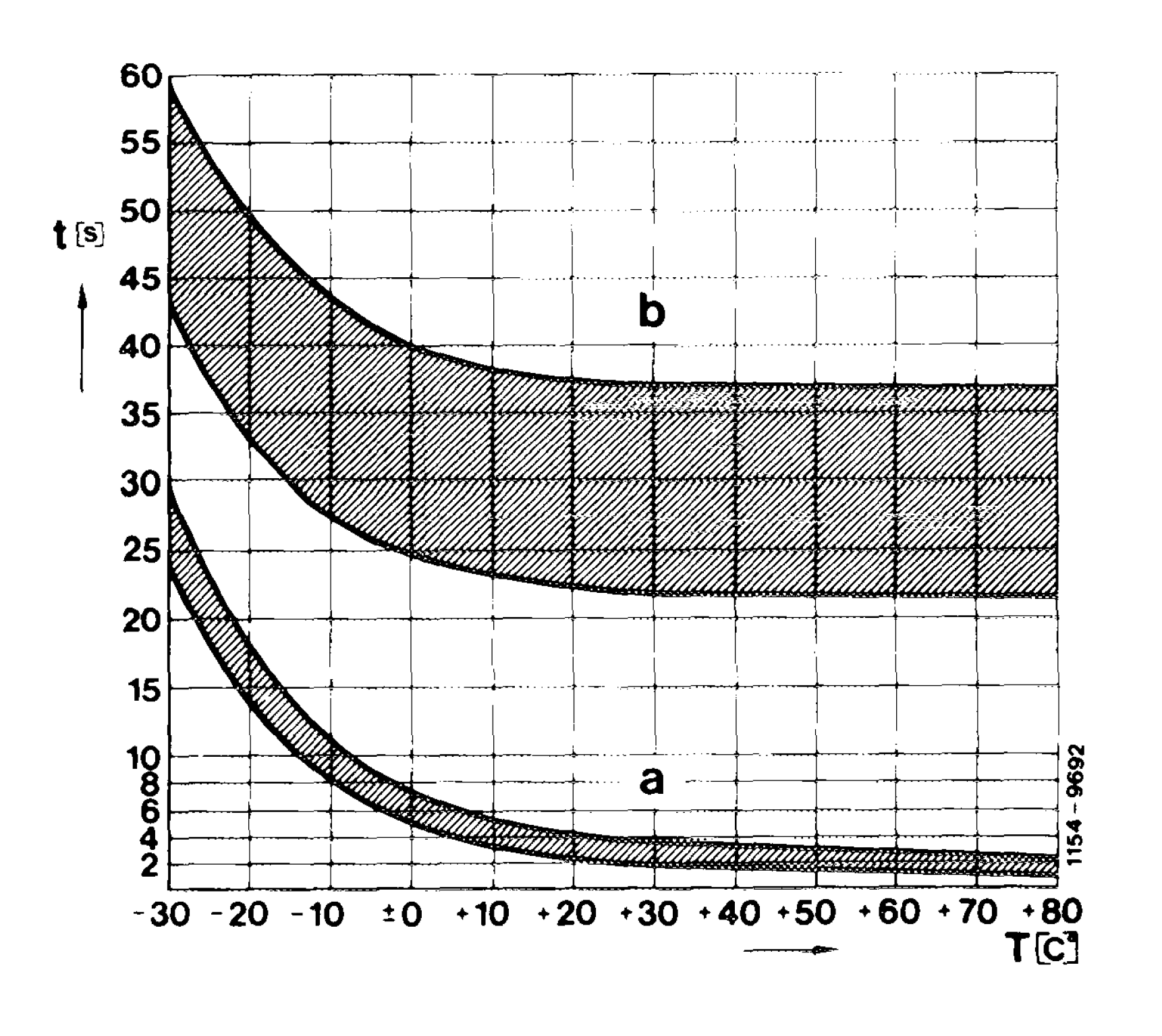
Below: The old curve (top) vs the new curve (bottom(a)).
In order for the microcontroller to know how long to glow the plugs, some conversion is needed. Since 8 bit microntrollers aren't designed to do lots of math, I went ahead and created a conversion array to map the 8 bit ADC value to the corresponding glow time.
One additional function that this controller retains from the original relay design: If the engine crank signal is detected before the glow plug timer expires, the plugs will turn off. Because this signal is 12V on the wiring harness, I used an opto-isolator to interface with the 5V microcontroller.
uint32_t glow_time = glow_data[adc_val] * 1000; // Convert to ms
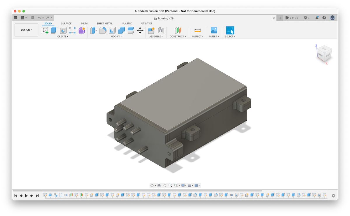
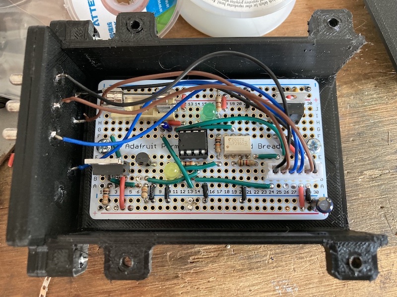
The last step (after soldering the sytem on some perf board) was creating a housing to hold the new relay. Time to fire up the 3D printer! Since it's going inside a car, PLA isn't going to cut it. Instead I used PETG, as my Creality printer can handle it well and I've had decent luck at prints lasting inside the car on a hot day. I carefully cut some of the pins off of an old relay that I had, and designed the enclosure's harness mating surface to encapsulate them.
After mouting the PCB and connecting the harness pins, it's time to button it up and install. So-far everything works well. There is a weird glitch when I switch on the AC compressor though. It seems the magnetic clutch current draw is enough to drop the voltage on the car's wiring just long enough to reset the microcontroller. This reset will fire the glow plugs for 1 second if the engine isn't yet at operating temperature. It only occurs when first engaging the AC compressor after starting the car, and can probably be solved by a larger capacitor on the incoming 12V supply to the LM7805 regulator.
The schematic and microcontroller source code for the project can be found on my github page here. Perhaps one day I'll design a PCB for the circuit. For now, the perf board will suffice.
-Eric